Material flow diagram
The material flow diagram defines how material moves from sources in the pit, through intermediate locations such as stockpiles and processes, to destinations like final products or waste dumps. Without a valid flow, material cannot be mined or moved, and the schedule will not run. If something is misconfigured, the affected item appears with a red outline or is coloured red so you can correct it before scheduling.
The essentials
A flow consists of nodes (locations) and movements (arrows that represent how material moves between nodes). Nodes model mine entities such as pits, stockpiles, and processing plants. Movements define the paths material can take and the rules that govern those paths.
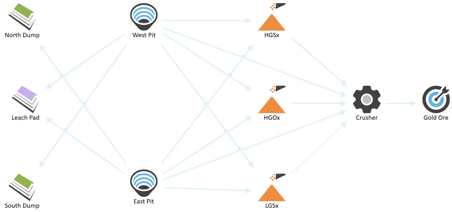
An example material flow
Material always originates from a source, such as an activity area within a pit node.
Activity areas assigned to a pit contribute to the pit’s totals. When allocating movements from a pit node, you indicate where the material will move to from the associated activity areas.
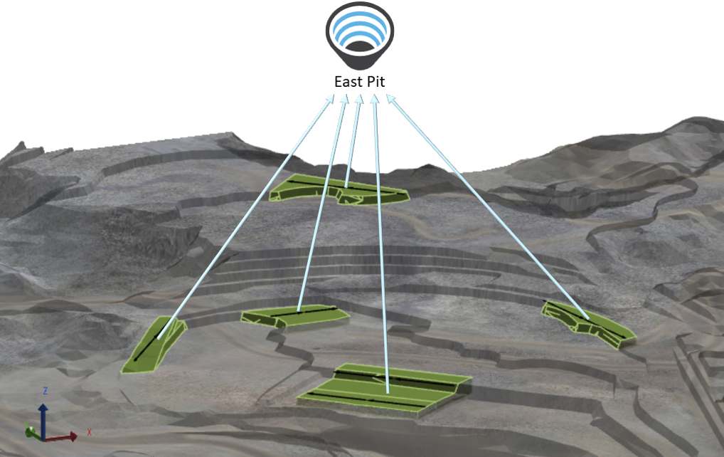
Pits are spatially defined by activity areas, while stockpiles and products are virtual locations. You can link virtual nodes to named locations in the haulage network to calculate travel distances and paths.
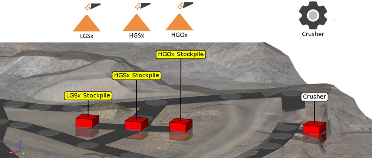
The named locations of stockpiles and the crusher from the haulage network within the 3D scene
After placing nodes on the chart, draw movements between them to represent material flow. For each movement, select the materials that can travel along it and configure related properties such as haulage method and priorities.
When multiple movements exist from a pit—such as to stockpiles and crushers—you can set priorities to influence scheduling. For instance, apply a negative priority to stockpile movements so the schedule prefers direct pit-to-crusher movements unless those become bottlenecked.
What you configure in the flow
Beyond nodes and movements, the diagram supports additional configuration:
-
Rehandle groups — Group movements from stockpiles or staged stockpiles for physical rehandling by loaders or conveyors.
-
Objectives — Apply quality or quantity targets to movements to guide the optimiser.
-
Calendar overrides — Adjust stack or reclaim rates per period for stockpiles and dumps.
Node types
|
Type |
Description |
|---|---|
|
The source of material to be mined.
|
|
|
A weighted average storage location. You can define its capacity, stack and reclaim rates, and inventory reconciliation. |
|
|
A stockpile with one or more piles that can each “build” or “deplete”.
|
|
|
A waste destination. Optionally import dump solids to visualise fill order and to use solid slice centroids for haulage destinations. |
|
|
A processing step (e.g., crusher, wash plant feed splitter) that can split and transform flow. Sub process nodes are supported. |
|
|
A specialised process node that appears when wash plants are enabled in Site management. |
|
|
A final destination representing saleable output. |
|
|
Group |
A container that shares inbound and outbound movements among its child nodes to simplify complex diagrams. You can’t group pits, products, groups, or processes that already host sub processes. Grouping is powerful but destructive to node level arrows (the group inherits and controls movements). There’s no undo, so consider cloning the site before large grouping edits. |
Build a barebones flow
-
Add nodes
Start with at least one Pit, destinations (Product and Dump), and optional intermediate Stockpile or Process nodes.
-
Create movements
From a node’s green border, drag to the destination to create an arrow. XECUTE names the movement from source > destination automatically.
-
Enable materials
On each arrow, tick which materials are allowed to travel that path.
-
Set capacities and inventories
For stockpiles/dumps, enter a capacity and add a reconciliation point that is on or before the schedule start. For early testing, set generous capacities to ensure a feasible solution; reduce to realistic values once it runs.
-
Decide haulage per arrow
Choose Modelled (uses HAULSIM routes), Fixed, No haulage, or a fallback travel time if no route is found; you can also drive fixed time with an expression.
-
Validate
-
Look for any red nodes/arrows and correct the configuration.
Working with movements (arrows)
A movement is where you control material eligibility, preferences, and haulage calculation.
-
Materials: The arrow inherits candidate materials from the source node. Select which ones are enabled to flow.
-
Haulage method: Choose:
-
Modelled: uses the imported HAULSIM model and named locations to compute travel time, including loading, spotting, and dumping components.
-
Fixed haulage: enter a constant time or expression (minutes).
-
Travel Time If No Route Found: the fallback value/expression if the model can’t find a route.
-
No haulage: skips travel time calculations for that link.
-
Example
For a Pit > Crusher arrow, choose Modelled haulage so the engine queries the haulage service for cycle times along actual routes. For Stockpile > Crusher rehandle, you might choose Fixed haulage if it’s a short, consistent travel.
Capacities and inventory
Capacities cap total material stored at nodes like stockpiles or dumps; inventories seed opening balances for qualities and tonnes. The optimiser needs these constraints to find feasible plans, especially when processes are rate limited.
-
Capacity: Typically a Mass limit (but any Sum type accumulation field can be used). Start large to avoid infeasibility during initial model build; then dial down.
-
Inventory reconciliation: Add manual checkpoints with measured date/time and values per principal field or ingest them via Data Feed In. The checkpoint time must be on or before the schedule start. Manual records take precedence over Data Feed In if they share the same timestamp.
-
Dumps with solids: When you import dump solids, capacity is derived from the solids and inventory records aren’t used; haulage destinations become the dump slice centroids for better realism.
-
Staged stockpiles: Piles maintain independent inventories and states (Building/Depleting). LIFO parcels (optional) track parcels with index/name and per parcel qualities and tonnes. Data Feed In can seed parcel inventories.
Haulage in the flow
When arrows use Modelled haulage, travel times are computed by the haulage service (HAULSIM engine), considering spot, load, and dump components and the nominal truck payload. You can also apply Dump Time Penalty on stockpile/dump/staged stockpile nodes to add a node specific time component on top of site defaults. For multi domain sites, map Named Locations per spatial domain so haulage knows which plant or stockyard location corresponds to a node.
Visual controls, selection, and layout
-
Create or copy nodes: Drag from the palette to create. Ctrl + left drag a node to duplicate it; the copy is suffixed with “n”.
-
Select: Ctrl/Shift + right click to select nodes; or left drag to box select. The selection box has a context menu to delete or group the selection.
-
Colour and shape: Change node accent colour to visually classify parts of the flow (for example, mine vs ROM vs product nodes). Reset anytime.
-
Control icons: Use the left hand toolbar to delete, zoom, open the Calendar override overview, and toggle Material, Rehandle Group, and Objective filters.
Material flow filter
Highlight one or more materials to see exactly where they can and can’t travel. Arrows with all selected materials enabled show bold; those with none dim. Click bold arrows to disable the selected materials for that movement, or click non bold candidates to enable. If you disable all materials on an arrow, it turns red to indicate an invalid movement.
Copying nodes
Nodes within the material flow can be copied and pasted.
- Select a node, then Ctrl + left-click + drag to copy nodes when the mouse button is released.
- The copied node name will be appended (n).
- All properties of the node will be copied (excluding node movement arrows).
Selecting nodes
Nodes can be selected by mouse clicks or dragging.
- Ctrl + right-click or Shift + right-click will select a node.
The selected nodes will appear with a blue border. - Left click + drag will create a selection box.
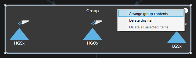
The selection box has a right-click context menu to delete or group the nodes as shown below.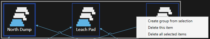
Grouping nodes
Nodes can be grouped by placing them into a grouping node. Once grouped, the child nodes share the inbound and outbound movement (arrow) properties of the group.
All nodes can be placed into groups except Pit, Product and Process nodes with sub-processes and Group nodes.
There are several ways to group nodes.
Add nodes to a group
- Click the group icon and drag a new group into the material flow.
- Create movements for the group.
- Drag existing or new nodes into the group.
Create a group from existing nodes
- Select one or more nodes. There are several ways to do this (multi-select nodes using Shift-right click, Ctrl-right click on the nodes or left-click and drag to create a selection box).
The selected nodes will appear with a blue border and bounded by a grey selection border
- Right-click in the grey-bordered selection area to bring up a context menu.
- Select Create group from selection to create the group node
This method will remove movements from the nodes when the group is created.
Group considerations
- Group child nodes inherit movements of the group, and nodes within the group do not have movements to other nodes within the group. As far as PO is concerned each child node is treated as if it had movements of the group node.
- Dragging an existing node into the group will remove the movements from that node and it will inherit the group movements.
- Dragging a node out of a group will apply the group level movements to the node.
There is no undo feature in Config. Consider cloning the site before doing complex grouping edits.
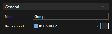
Group controls
A group has name and background colour properties. Select the group to open the properties box
The group context menu includes an entry to Arrange group contents when more than one child node is present.